Process Documentation


First, we did research into the enigma and the inner machinations of the rotor system.
Resources:
http://enigma-replica.com/index1.html
https://www.cia.gov/news-information/blog/2016/who-first-cracked-the-enigma-cipher.html
https://hackaday.com/2016/10/21/3d-print-an-enigma-machine-thats-close-to-the-real-thing/
http://www.instructables.com/id/Make-your-own-Enigma-Replica
http://cryptocellar.org/Enigma/http://www.matematiksider.dk/enigma_eng.html
Next, we made our first simplified prototype for the device. For each iteration, I made separate circuit diagrams in order to troubleshoot and optimize our electrical layout.


We found that more space was needed for the wiring, as the soldered connections tended to break, and once sealed the part could not be worked on. Additionally, we found that by putting the LEDS in opposition, the current could continue to travel in the intended direction, through and back again, and light the correct LED. The metal rod in the middle was used as our ground.

Second Iteration 
Contact plates
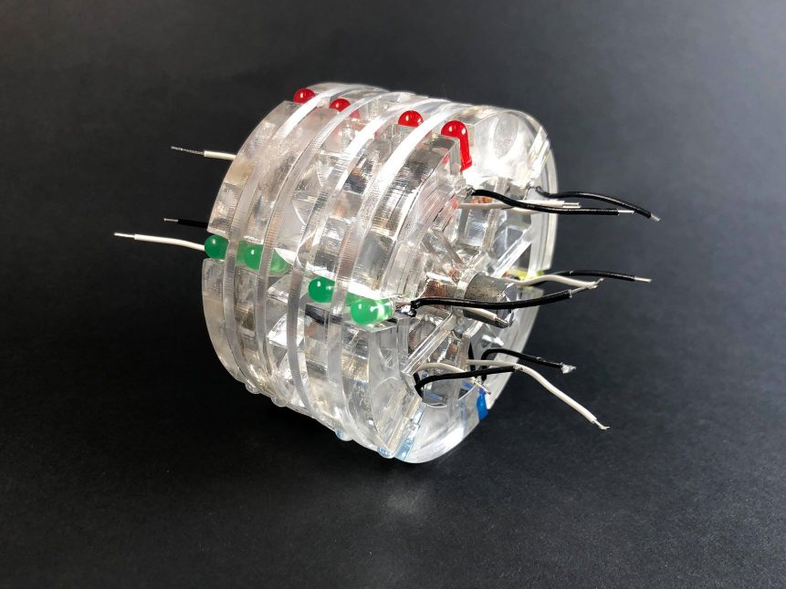
For the second iteration, we expanded upon this idea. We chose 8 LED colors to be representative of a character. The scramble across the device is shown in this model, and is hardwired from R->G,B->Y etc., internally to represent the hard scramble in each rotor. We found this model also suffered from breakage issues, and when the contact plates were attached, there was interfacing issues between individual rotors. We also found a strong external power source was needed for the very high resistance.


Final Iteration
For the sake of ease of display and maintaining sufficient contact between the rotors, we switched to a series of LED strips that were color controlled by an Arduino. We cut down to 6 inputs and added an input remote. This allowed for easier viewing of the physical cipher, more consistent contact when rotating the rotors, and the ability to do maintenance. The final iteration was also closer to the actual internal wiring than our earlier prototypes, as the led strip replaced the single wire between sides.
This project taught many aspects of the prototyping and design process in a more serious and performance-based environment. We had numerous designs which all would have worked with ideal situations. However, as encasing and other physical constraints came into play, some designs proved to be impractical. For example, we initially intended to use fabric wrapped in copper tape to conduct between the rotors. However, this had very low tolerances since the parts were very small and could only compress so much. The physicality of our intended LED display was also made impossible due to physical constraints. Since everything had to be glued together with our old design, a small break within the interior of the rotor made it impossible to use.