Process Documentation
Interview with the Client
For this meeting, we were focused on getting to know the client, and finding out some areas where he felt his life could be improved by our making of some sort of device to help him in that area. We met at the clients apartment.
Agenda
- ICEBREAKER – tell him our names and majors, and why we took Physical Computing. Ask why he chose to participate in the OSHER class he’s taking and this particular project
- Explain project goals/answer questions he might have, explain timeline of project
- Give examples based on our assistive devices of what an assistive device can look like.
- Adapt below questions based on where our conversation leads us:
- Ask him to walk us through a typical day (or, specifically, what he did today), and show us around his apartment if possible.
- Are there any activities in your daily life that are difficult or frustrating? Maybe have him walk us through what stresses or frustrations he’s had today
- What’s something you used to enjoy doing which has become harder with age?
- Once we narrow down to one or two pain points:
- Could you walk us through that activity?
- Draw a map of the steps through that activity?
- Draw/model a “magic” device that could make it easier?
- Wrap Up – Take any needed extra pictures/documentation, say thanks
Summary + Major Takeaways
When we spoke to him, the client already had some ideas for areas in which a new device could be beneficial. The two areas of interest were something that would help position his iPad when he was using it to draw on the couch and could track the time he’d spent working on it so to make better estimates for his jewelry commissions, and something that would help him with his hydroponics system. We decided to focus in on the device for his iPad, as that was the area where he felt like there wasn’t already an exact solution for it.
While he draws, he often has to tilt and position his iPad in different ways to get the right angle to draw from. He typically keeps it on a pillow and props it up with his hand, which doesn’t allow for it to be fully stable, and makes drawing harder. He tries to keep track of the time he’s spent working on each commission in order to keep pricing fair and know for future reference how long similar designs take.

At night, the client sits on the couch with his iPad on a pillow on his laps and draws for jewellery commissions while he and his wife listen to the news. During this process, he has to move and tilt his iPad around to draw, which he finds a bit cumbersome. He was interested in some sort of lap desk-type-thing that would help do some of this work for him.

Some features he was interested in having for this holder included
- Something to help with positioning his iPad – preferably digital, since he said that he could already move it with his hands
- A slot for his pen
- Something that would keep track of how long he’d been drawing for reference when making invoices for his jewellery commissions

Thoughts
Because the client had thought about the prompt beforehand, our meeting with him deviated from our original agenda in that it was a lot more direct – we didn’t have to spend a lot of time identifying the problem area. While the client gave us a fairly clear cut idea for what he wanted, we thought this project could pose some interesting design and technical challenges, in terms of the creation of the actual objects and setting parameters for the motion. I think next time I would have liked to have him draw what he was generally looking for, and have us as a group add on to it to think of more possible features. Overall, we all thought the meeting went well and was very productive.
Initial Prototype
Our first prototype gave the client a sense of the scale of the final product, so as to demonstrate both the movement of the board and to understand and look critically at the experience of using the device to assist you in drawing on an iPad. The stand attaches to the back of the board and sits on a table, where it can be moved up and down to better suit the clients desired angle of drawing.


Many of the challenges we faced during this process involved getting the right parts to mount the board on. We knew that finding a combination of parts that allowed easy movement using a joint that wouldn’t collapse under the weight of the board, while positioning the board in a way that it wouldn’t tip over or rest too high above whatever surface it was placed on would be difficult, so we tried to focus on the mechanical aspect of this prototype. It took us a long time to find the right parts to order for the joint, which delayed our finding a good way to attach the joint to the board properly, and multiple different iterations of how the client would interact with the LCD interface delayed us in getting a functional electronic prototype.
In order to be able to use the LED displays already available in the physical computing room, which display text in clusters of pixels and can only allow text inputs in a constant size, we created a system with 7 buttons, allowing us to have a constantly defined button for each conceivable purpose, including three buttons labeled as three different projects. Initially, we envisioned the working projects as simply being numbered as project 1, 2, and 3, but then decided that a record of previous projects would be an important part of the purpose of tracking the time for each project. When a project was completed, the next project should be labeled #4 and so on. Since the buttons for projects 1, 2, and 3 were to be labeled with those numbers and placed in order, we reasoned that this would be confusing when, for example, project 2 was completed and the list became 1, 4, and 3. Additionally, past the first few projects, the numbers corresponding to different past projects would no longer be reasonable to remember, so we decided to add a method of naming each project. We looked for Arduino compatible keyboards but decided that that would be an unnecessarily large component that would not fit into our already designated dimensions of the physical board. Instead, we added a rotary encoder, programmed to enter text letter by letter. We also decided to purchase a TFT display and created code that would allow each button to be labeled on the display, allowing us to cut down to 3 buttons.
While during the initial crit we didn’t have much time to get questions from the audience, we got helpful feedback from the client regarding ways to make the form easier for him to use, such as adding a finger slot to the side of where we milled a place for his Apple Pencil to rest, and rounding out the right edge of the board so that his forearm wouldn’t chafe when he was drawing. He experimented with angles at which he would usually hold the iPad, and found that the fit was secure, but asked if we could add elastic on corners or hollow out the space below the top edge for a snugger fit on top when the iPad is at a high angle. We were also able to ask him more specific questions about his habits around taking commissions that we weren’t able to ask during our initial meeting because we hadn’t fully settled on an idea to probe more into the behavior around it; for example, he told us that he works on around 5 at a time, and would like to have them labeled in the system, supporting our choice to shift from constant buttons assigned to three projects at once to a menu system.
It would have been helpful for us to have at least some of the circuitry and software finished so that we could see if he felt comfortable interacting with it, and able to understand the basic mechanisms and instructions to use it. While we showed him paper sketches of what the interface and surrounding hardware would most likely look like and how it would be used, and he showed no issues in understanding how it would work, it would have been helpful to have had some part ready for him to interact with. Often hearing how something will work is easy to understand, actually using said thing is often when problems arise.
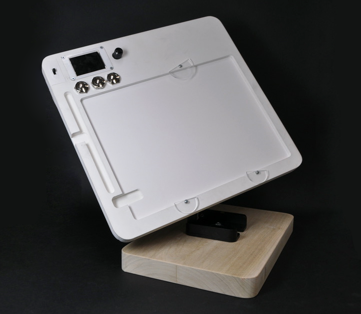
Final Prototype
It was challenging to update the design for the final mill into the new plastic we were using because of time restraints. Because of the line to use the CNC machine, we needed to submit the final mill file the day after we got the prototype fully milled for it to be finished in time. The other was that we weren’t able to get our electronics wired together as quickly as we’d expected due to software issues, so we weren’t able to mount them into the MDF prototype and actually test all of the components together as we’d initially hoped to.


When we milled the back of the MDF prototype, we did our best to gauge what measurements were correct and which should be changed. WE realized it would be difficult to mill at a depth where everything would be submerged in the material, and changed the design for the back to include a larger pocket for the electronics to be drilled into. Because of this, we could no longer plan to just screw an acrylic cover over the components and instead began to plan a vacuum-formed plastic piece that would cover the components.


A lot of finishing work went into the design, including rounding all the edges and sanding both the base and the top board, and spray painting the top, making a paper backing to cover the t-screws holding the top board in place, and paper, acrylic, and vacuum formed styrene covers for the electronics.

Due to wrong initial dimensions and changing components, some of what was milled needed to be altered. This was done by dremmeling the pockets/holes until they were roughly the desired size/shape. The screen pocket was just an issue of depth for the component, not for its acrylic cover, a deeper pocket was dremmeled for the component, then a glue specifically for acrylic to bond the component to it’s cover was used and the cover was screwed into the plastic.

We encountered a lot of issues with the electronics, particularly after we’d solder them all together. We’d initially soldered all of our wires into the Arduino, but after we continued to have problems, we ended up cutting the wires and moving back to sticking the wires into the header pins mounted on the Arduino.
When working on developing the display software, we encountered difficulties with the internal arduino timing and the rotary input

After many hours analyzing the code to determine what was causing issues with our rotary input, we determined that it was due to a library conflict, and rewrote the code to utilize a different library- resulting in an encoder that “worjs”.

Conclusions
While a lot of the feedback we got from the crit revolved around things we already knew were issues – in particular, that “some components weren’t secured/working right”, and that because our ball socket wore out during the crit the top board was “floppy”, some of the feedback brought up things we hadn’t even considered. Someone brought up that we should “consider whether the client was right or left handed” because our current positioning of the electronics was on the left side of the board.
Two people brought up the issue that maybe using an app or timer already on the iPad would be more effective, with someone saying that “the UI for tracking projects was clunky and would be better solved by an app on the iPad”. While this is a good point, and there may be more sophisticated timer options in the app store, this was something we’d talked about with the client when we’d first met with each other, and while he acknowledged that it was something he could do on his iPad, he liked the idea of it being somewhere he wouldn’t have to minimize his drawing app to access.
It was interesting to work with the client and to create something that tailored to his needs and interests specifically. Making something for the purpose of a crit is very different from the process of making something to last someone for a while. I think if we were able to get a stronger ball and socket joint, as the one we used wore out incredibly quickly, the mechanical and design aspects of this project would last a good amount of time and be reliable for him to draw on.
We went into this process thinking both the design and the electronic aspects were a lot less complicated than they actually ended up being, and so we didn’t front-load the work as much as we should have. Our design elements ended up needing a lot more finishing work than was initially expected, and because we were handing it off to a client as opposed to it just being for crit, I felt more compelled to do the work to make it look nice and functional. If we were to do this project again knowing what we know now, I think we would make a big effort to frontload as much as possible, and get electronics and a basic design prototype in place as quickly as we could so that we could focus more on testing and making this stable enough to last the client a long time.