Process Documentation
Initial Stages
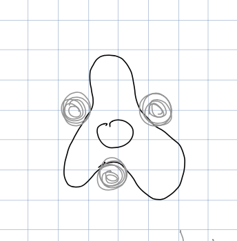
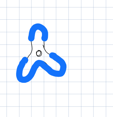
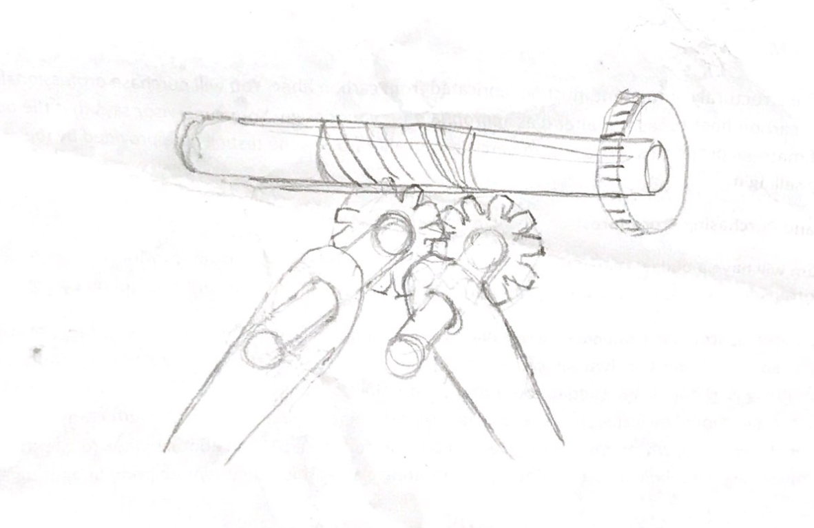
We first did some rough brainstorming about different ways to grab the object.
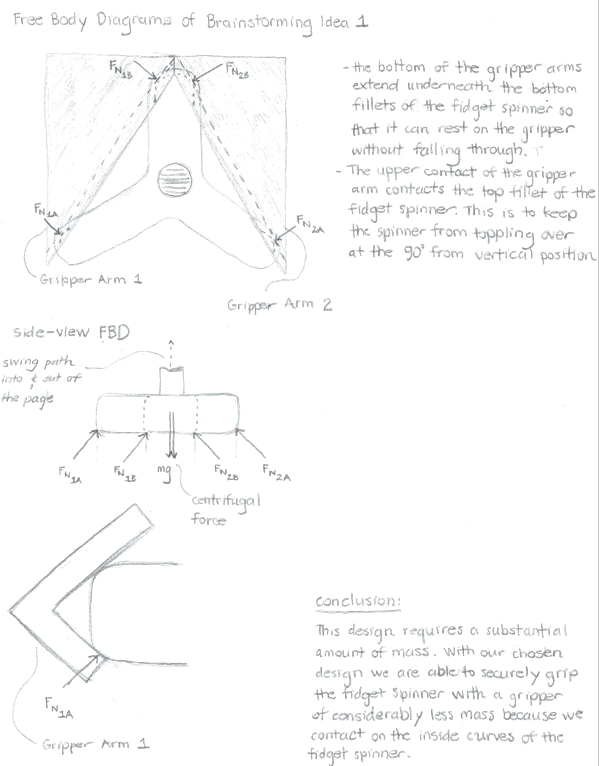
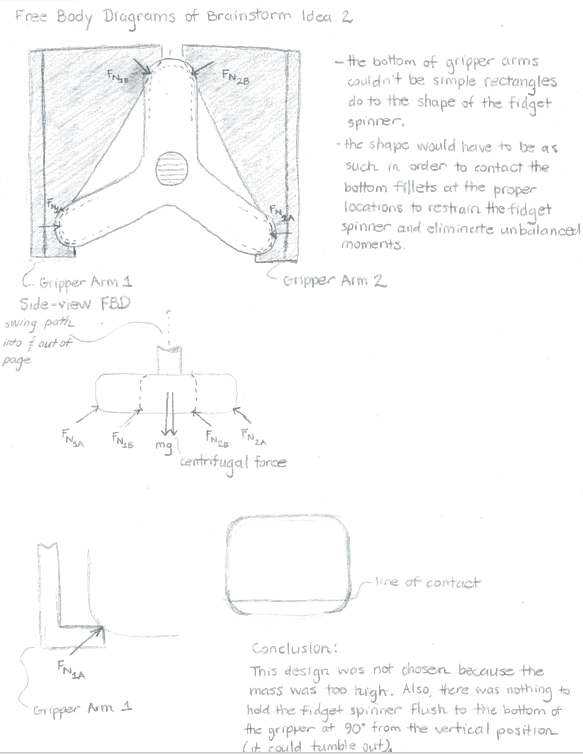
After the initial stages of brainstorming, we picked two ideas and did hand calculations for them to determine the forces needed to hold and maintain grip on the object.
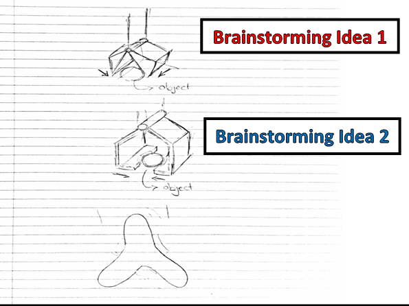
We brainstormed some more and optimized a design that would allow for easy gripping, lightest weight, and acceptable forces.
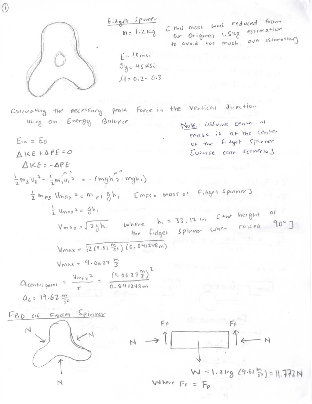
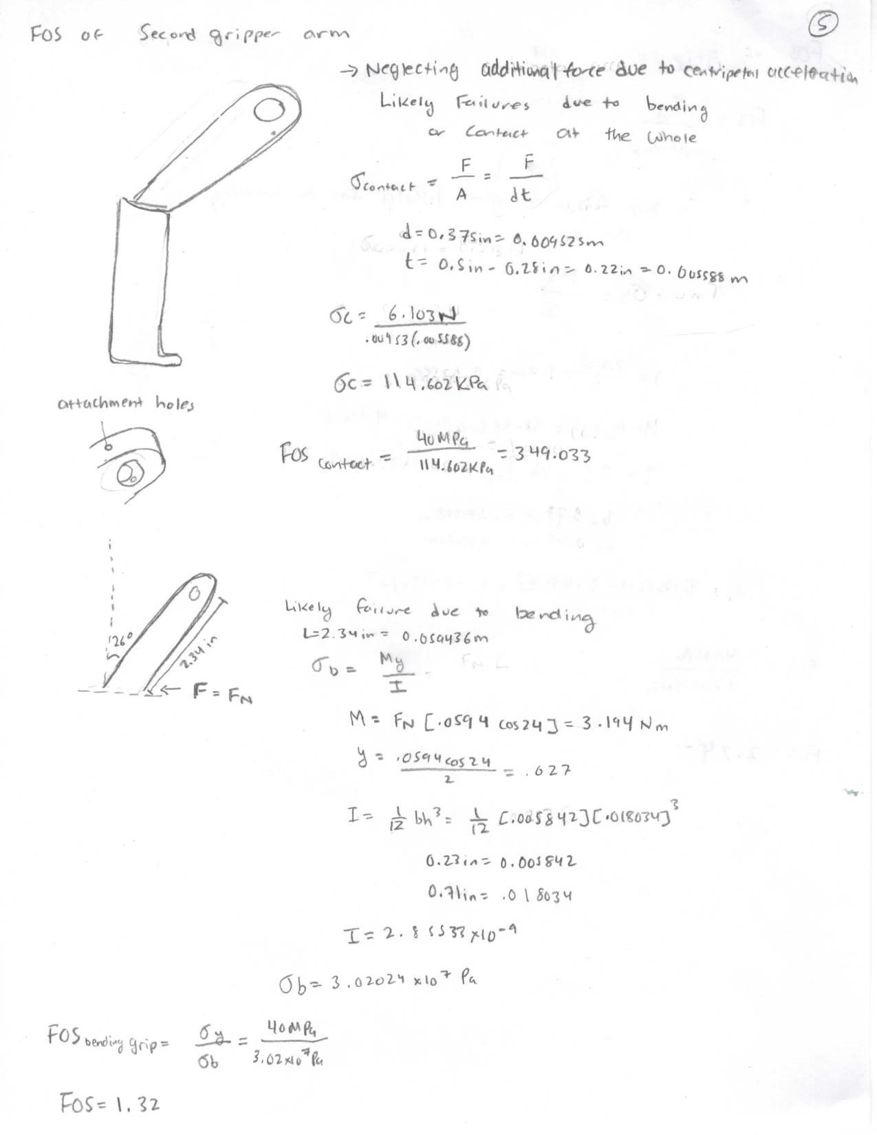
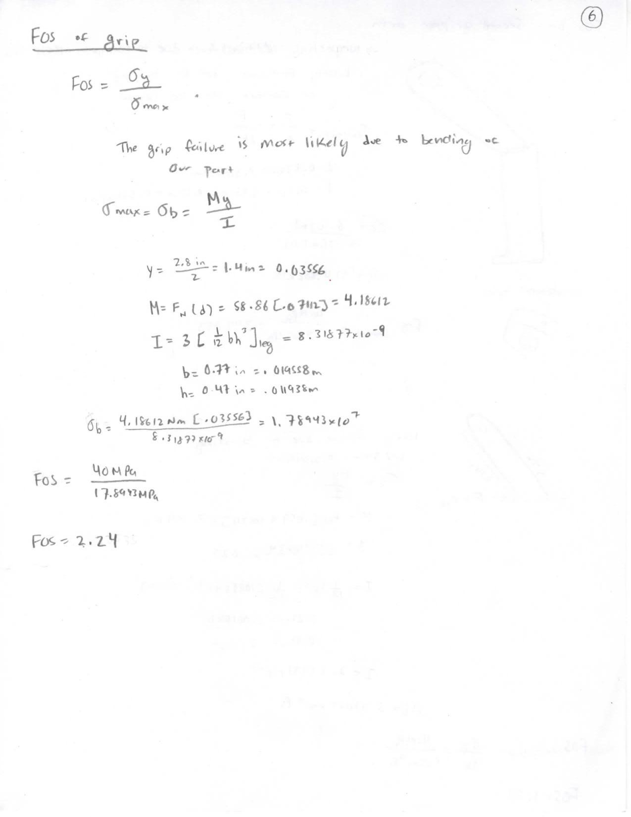
Calculations for Final Design
Detailed Model Analysis
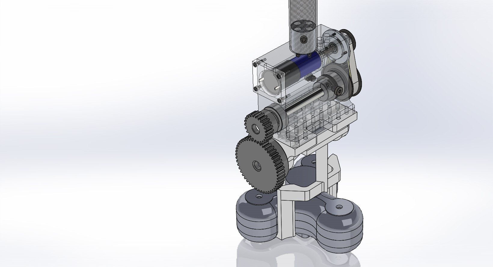
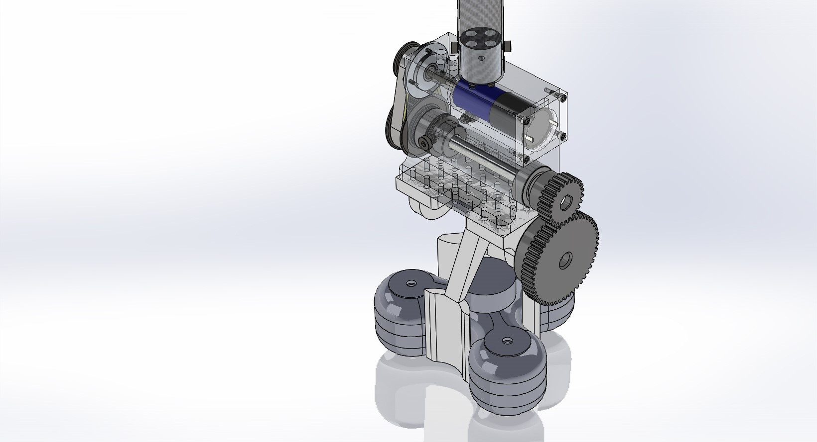
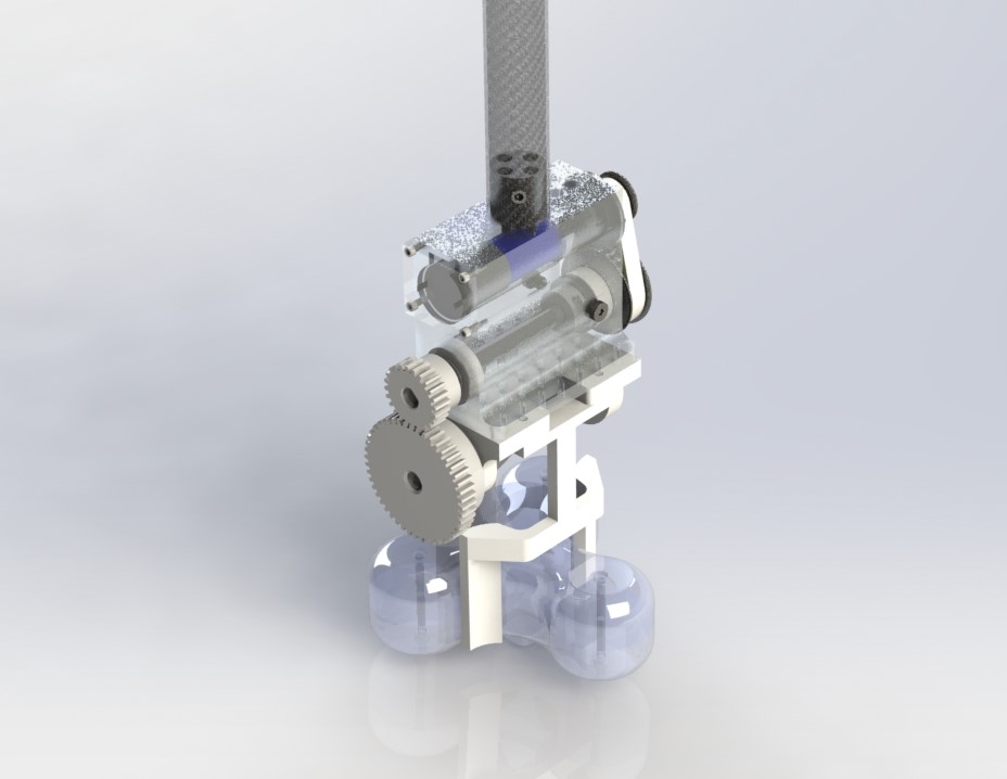
The assembly was modeled and optimized in Solidworks and consisted of three parts that attached to the swinging arm, the box, moving claw, and stationary claw.
For most of the custom made parts on our design, we decided to use ABS as the material to manufacture our parts.
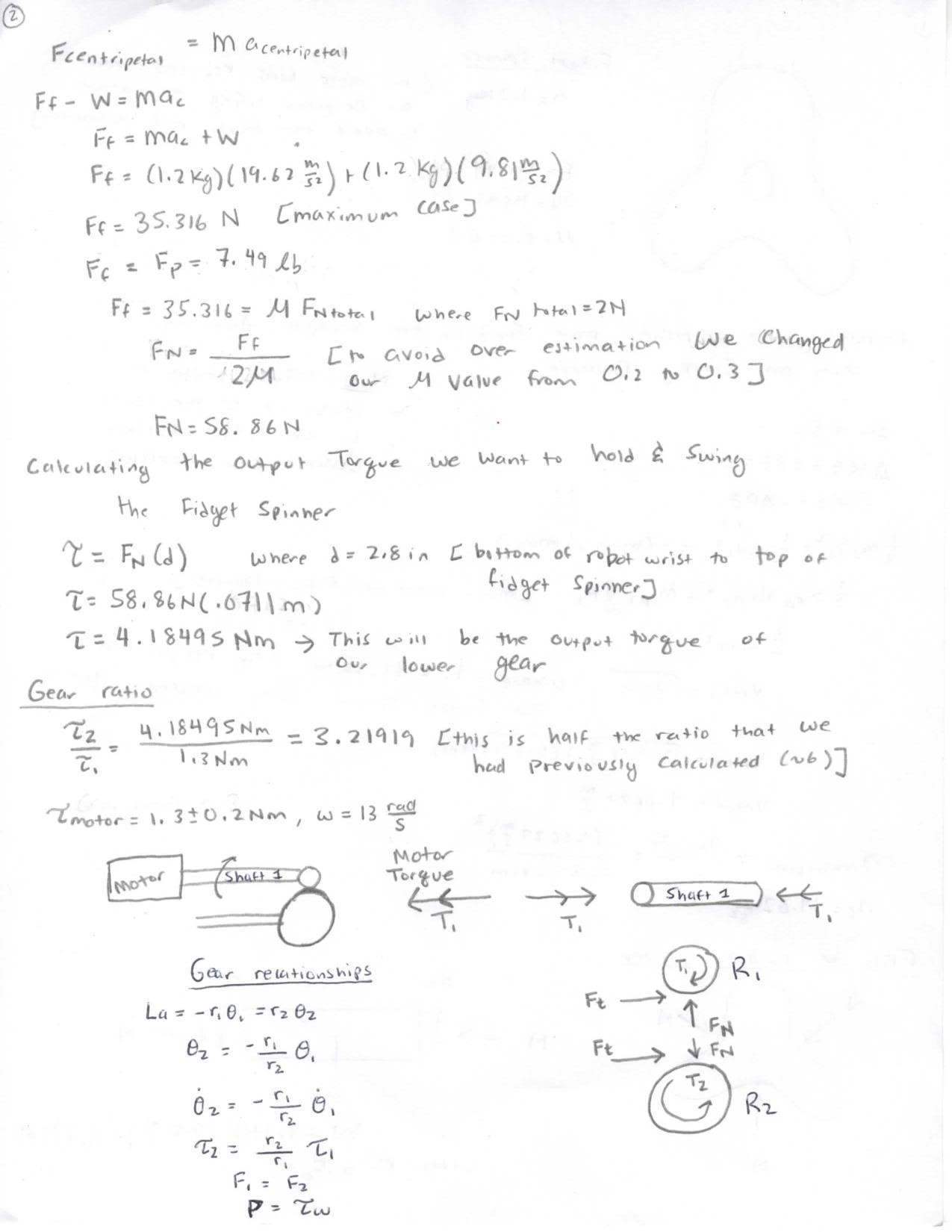
For the claws, we needed something that could withstand high stresses and increase the coefficient of friction between the gripper and the aluminum fidget spinner. Using ABS increased our coefficient of friction from .2 to about .4, which lowered the amount of force we needed and lowered our gear ratio.
ABS was chosen for the box attached to the plate of the motor because we could print quickly and for a low price. We didn’t anticipate a lot of force was going to be applied to this component, so we went with something relatively strong in case something wrong occurred.
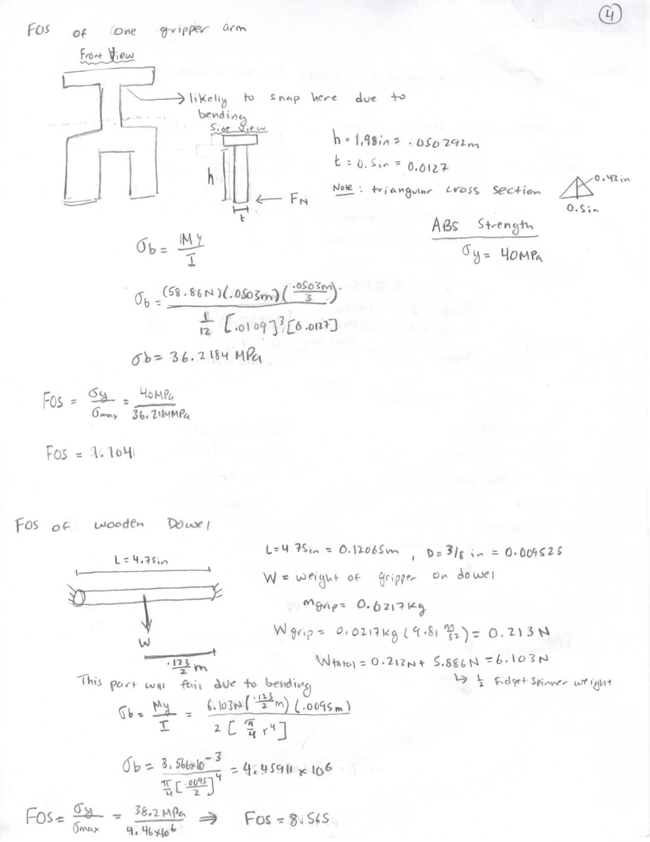
For the shaft, the material selected was a wooden dowel, specifically poplar wood. We found this material to be suitable for our needs because of the wood’s high modulus of rupture. This was also a lighter and cheaper alternative to the steel shaft we had originally planned on using.
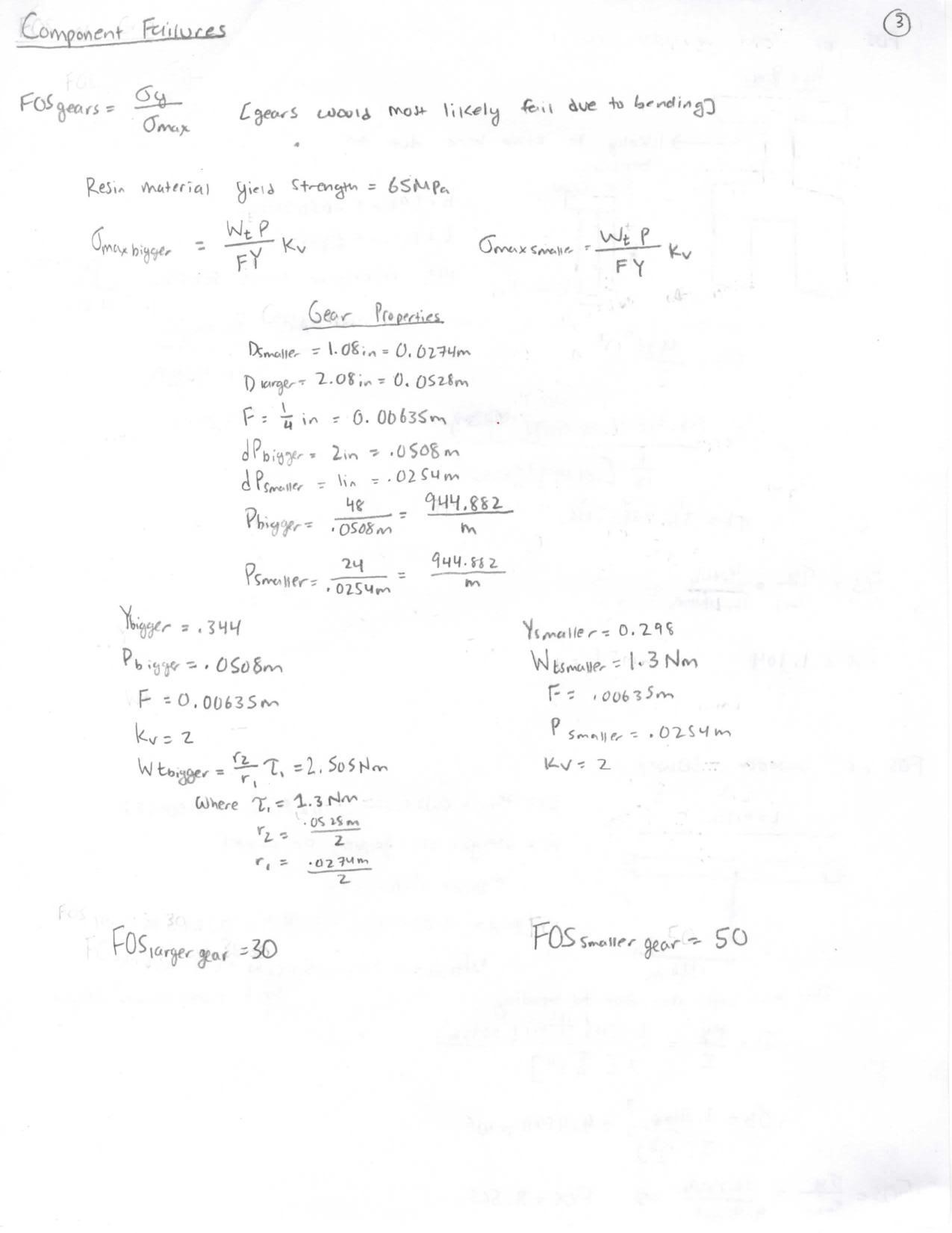
Gears were 3D printed using the resin in the Form2. Catalog gears made from metal were convenient, but they were heavy and expensive. After looking at the material properties of the resin, it was clear that it was going to be a strong, inexpensive, and light alternative to metal gears.
Main Components
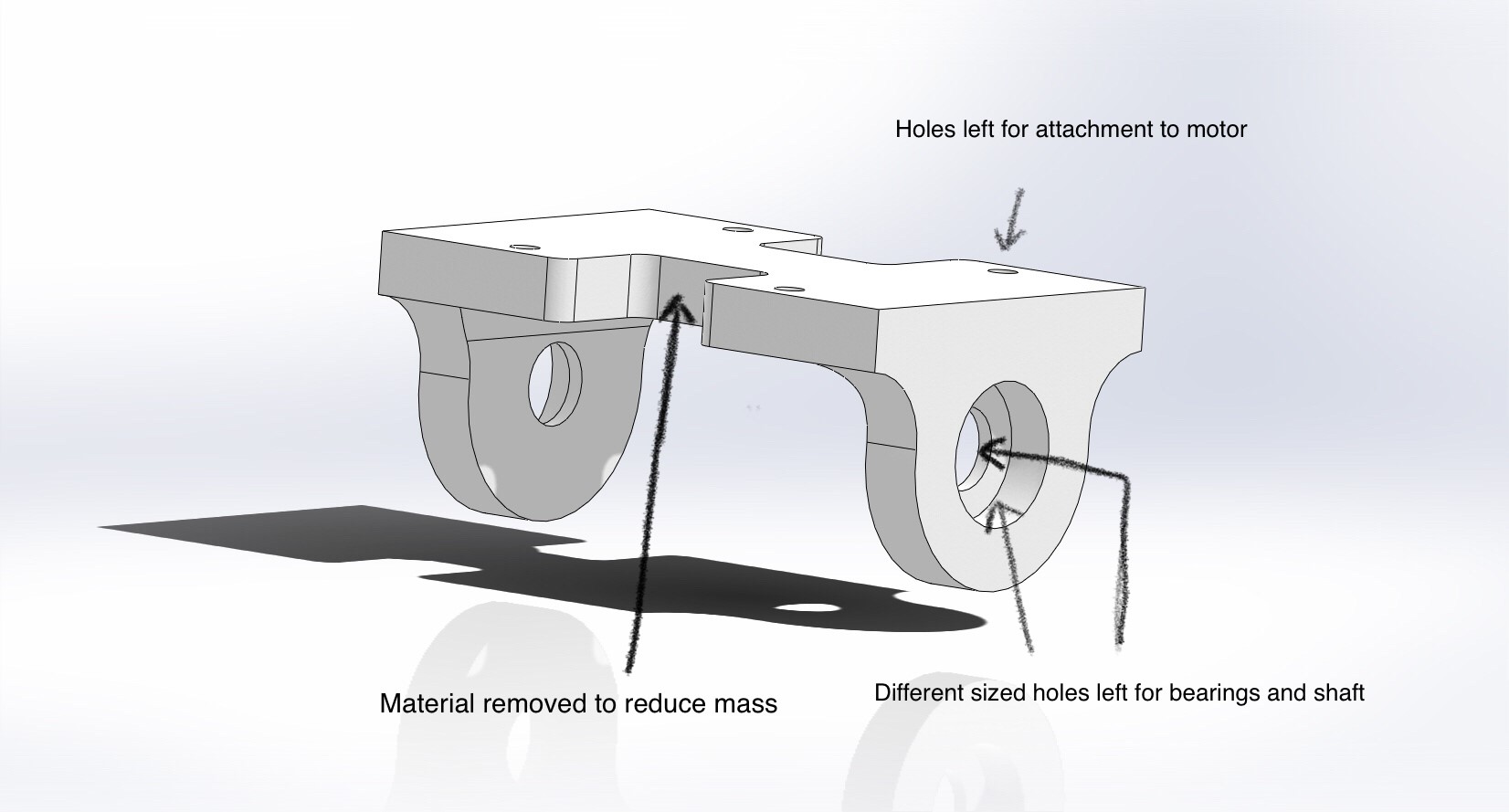
The box is designed to be a point of attachment for all the moving parts of the gripper. It also serves as an attachment for the gripper to the motor. There are holes on the sides for the shaft to go through and holes at the top for attachment of the stationary arm and entire gripper to the motor.
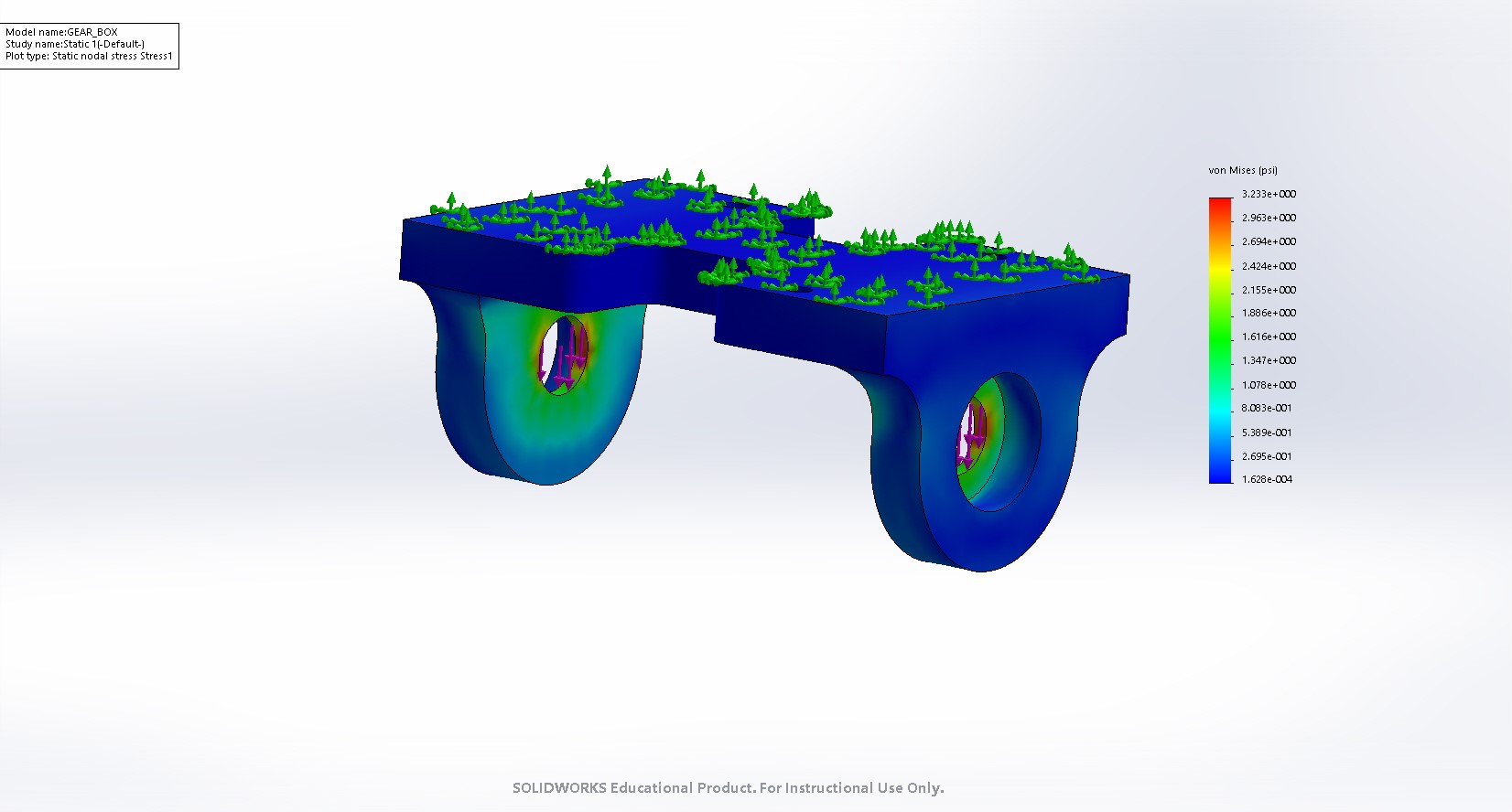
The part was analyzed in CAD through running a static simulation where the top was fixed and forces placed at where the shaft runs through the box.
● Material: ABS
● Mass: 68g if solid
● Cost= $5.00
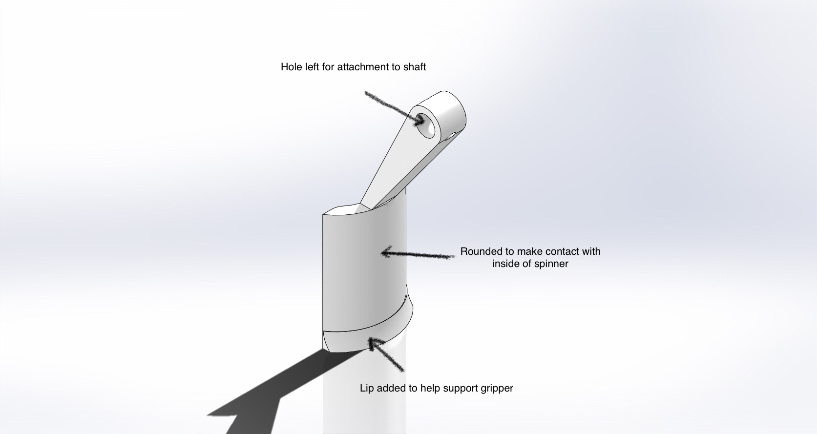
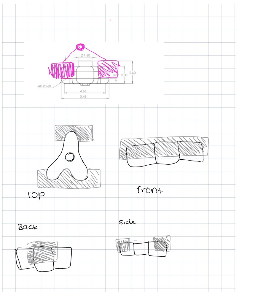
The moving claw was has a hole for attachment to the moving shaft and has a foot at the end to help provide support at the fillet of the spinner. The gripper has a curved section to make as much contact with the spinner as possible.
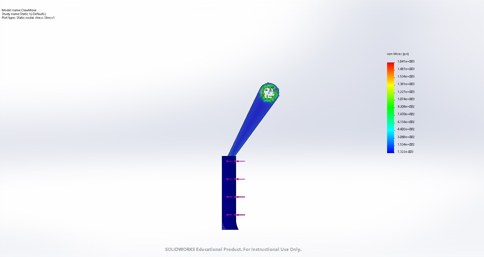
The part was analyzed in CAD by fixing the hole where attachment happens like a hinge and applying a torque to the part that makes contact with the spinner.
● Material: ABS
● Mass: 23g if solid
● Cost $2.50
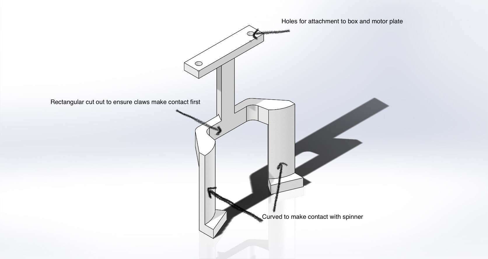
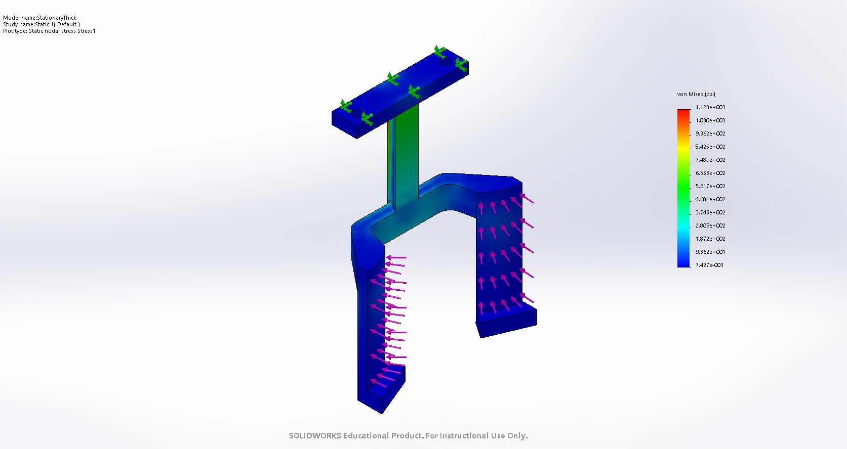
The stationary claw has two points of attachment to the box and plate of the motor. Both parts of the claw that make contact with the spinner are curved to maximize contact area. “Feet” were added to the bottoms of the claw to provide extra support at the fillet of the spinner.
To analyze this part, we fixed the top of the claw and applied a force both parts of the claw that make contact with the spinner.
● Material: ABS
● Mass: 32g if solid
● Cost= $5.00
Additional Components
Wooden Dowel:
We used a wooden dowel for the shaft that ran through the gripper because we thought that the mass and strength of the wood was suitable for the needs of our design.
Bearings:
Bearings were used to ensure that the shaft and mobile arm have a smooth movement when opening and closing around the spinner. The bearings also keep the shaft aligned. The pair of bearings that we picked were selected because of their light mass and ability to press fit onto the shaft.
Friction Tape:
Friction tape was chosen because we wanted something that would increase the coefficient of friction between our gripper and the spinner which would decrease the gear ratio we would need. We picked this material over other materials that could increase the friction and stay cost effective.
Screws:
Screws are needed to attach the gripper to the plate of the motor and for making sure that the moving arm stays in place on the shaft. We decided on screws based on the motor’s plate. Another decision factor was the length of the screws.
Gears: Gears were selected based on the gear ratio we wanted and the constraints of the shafts. Due to the weight of the gears when ordered directly from McMaster, we decided to 3D print them using the Form2. This left us with a design we were confident in that was also light.