Duration: 15 hours
Team Members: 3
Skills Applied: Mechanical Systems Analysis
Tools Used: Drill, Drill Press, Metal Shears
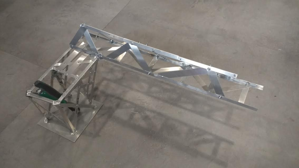
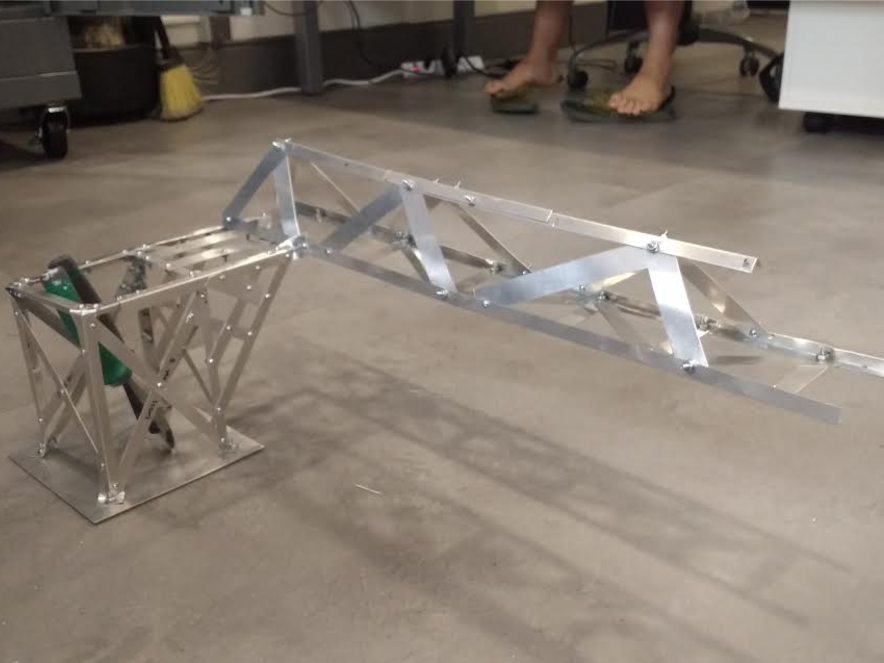
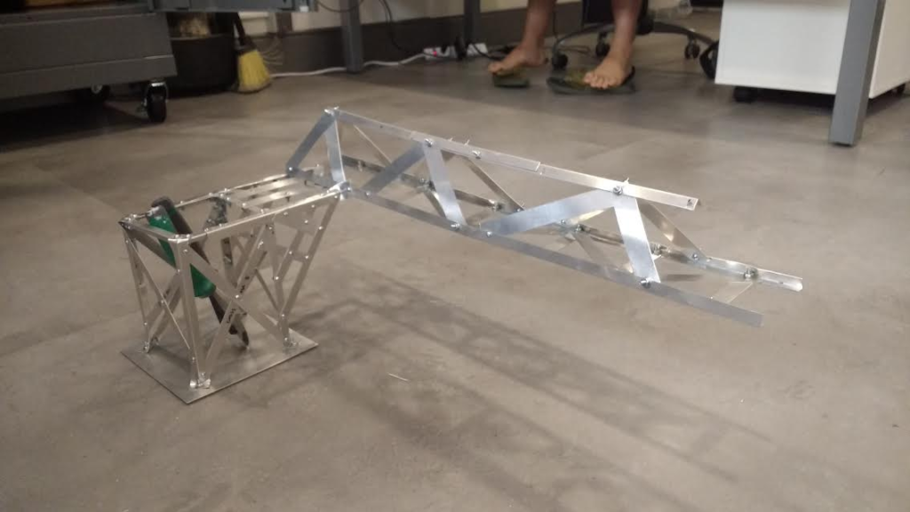
The purpose of this project was to build the lightest crane with a motor and lever arm at the end that could lift a one-pound weight the highest without deflecting and touching the bounds. This project was done in a team of three.
Theoretical Servo Torque calculation:
- Object Weight: 1 lb = 16oz
- Max Torque: 57oz – lb
- Theoretical Maximum Arm Length: 57/16 = 3.56 inches
- Real Arm Length = 2 inches
- Theoretical weight lift: 2 inches
- Theoretical torque output necessary: 32 oz-in
Theoretical Lift distance
- Assuming there is neglectable deflection on the structure:
- According to the geometry:
- The distance from the pivot point is 2 inches
- Assuming the turning angle of the servo is 90 degrees
- The distance of lifting would about:
- According to the geometry:
sin(45) * 2 * 2 = 2.83 inches
- Assuming we were able to use the full 57 oz-lb.
Theoretical Loading Calculations:
- Length of the triangular arm = 26 inches
- Size of the base = 6” x 6”
- Normal distance between lifting hook and clamp = 12 inches
- Calculation of torque that the triangular truss produce on the base:
26” x 1lb = 26 inch-lb
- The max force that the clamp should supply on the far end clamp is:
26 inch-lb / 6 inches = 4.333 lb
Discussion:
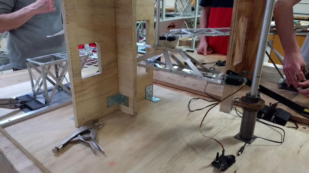
- Discrepancies that occurred:
- The material that links the base to the triangular truss buckled significantly during testing.
- The mounting setup for the motor actually prevented the weight from being raised further.
- There was not much space to attach the motor, so it is in a very small area. Therefore, we did not have a long enough lever arm for the counterweight to be effective.
- Consequences of discrepancies:
- The linkage buckled significantly and the end attachment to the motor deflected about 1 inch. In turn, the servo did not lift the weight as high as it should have.
- Due to the mounting setup, the servo is not able to continue turning after lifting 1 inch.
The arm for the counter weight was too short, rendering the counterweight more ineffective. Therefore, to have more of an effect, we added a larger counterweight and ended up adding a lot more weight onto the system. Overall, this design could have been much more successful.