Duration: 30 hours
Team Members: 6
Skills Applied: 3D Printing, Mechanical Systems Analysis, SolidWorks
Tools Used: Ultimaker 3D Printer, Form 2 Printer
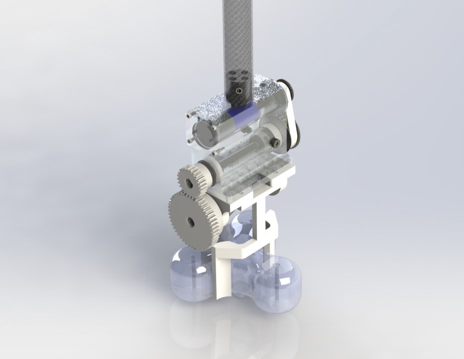
The aim of this project was to design a gripping device that would attach to a swinging 1-meter arm that had a motor affixed at the end. The gripper had to maintain a grip on a large steel object throughout several swings in a 180-degree arc. The object weighed 1.2kg and was shaped vaguely like a fidget spinner. The gripper was optimized to obtain the lightest weight.
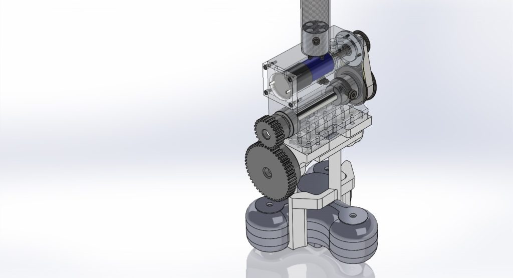
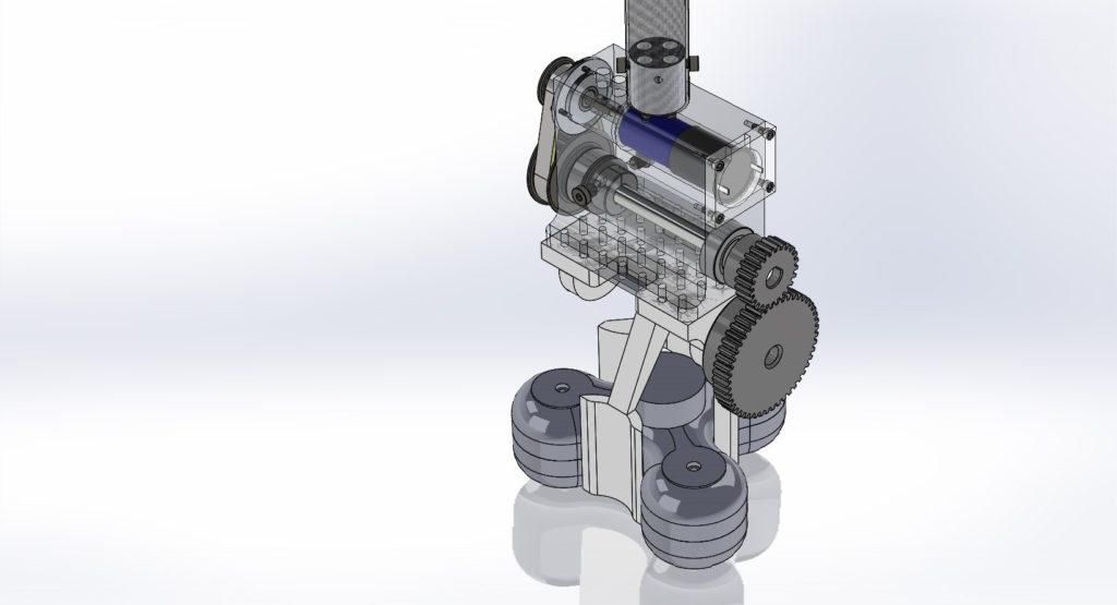
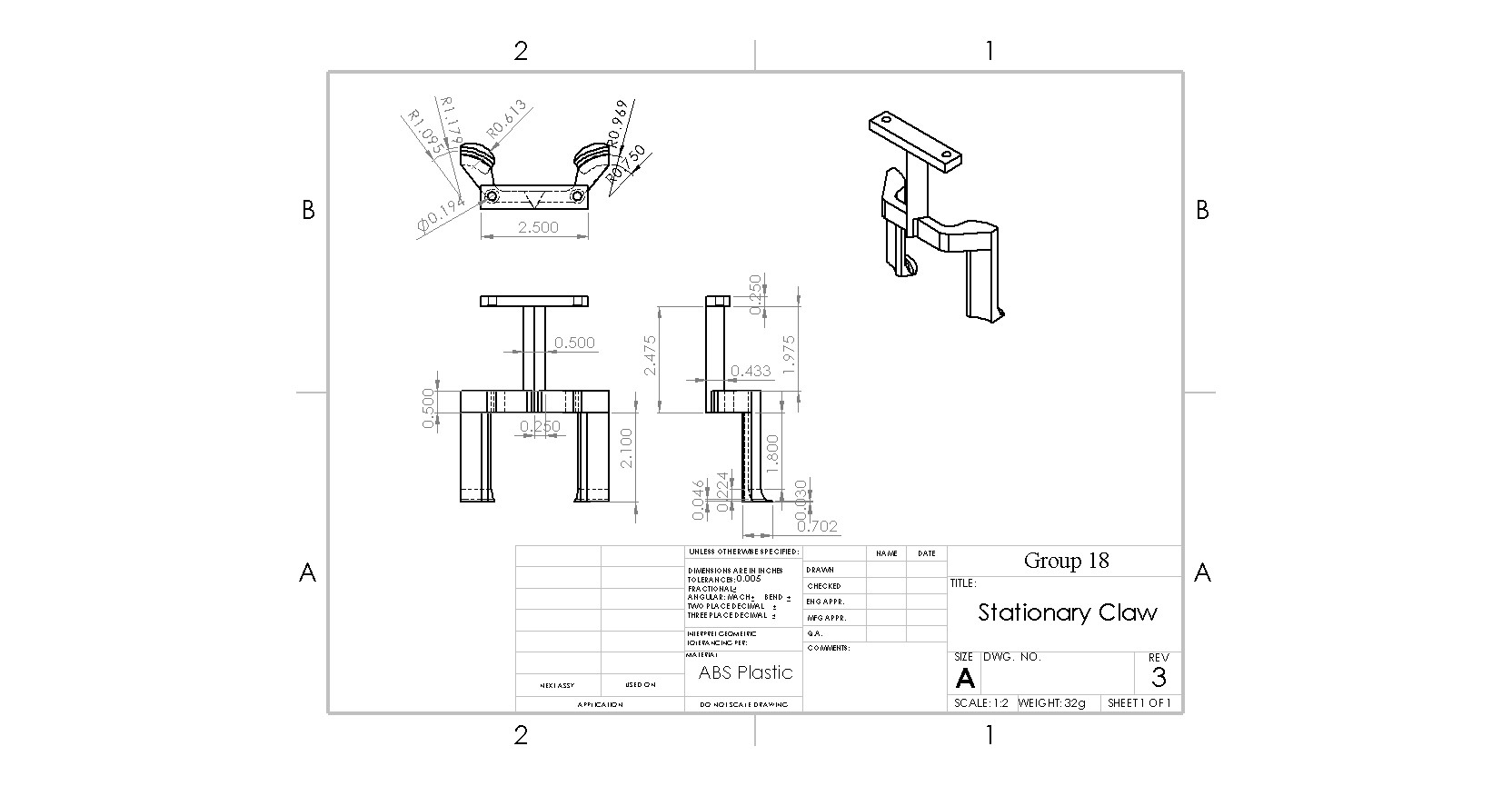
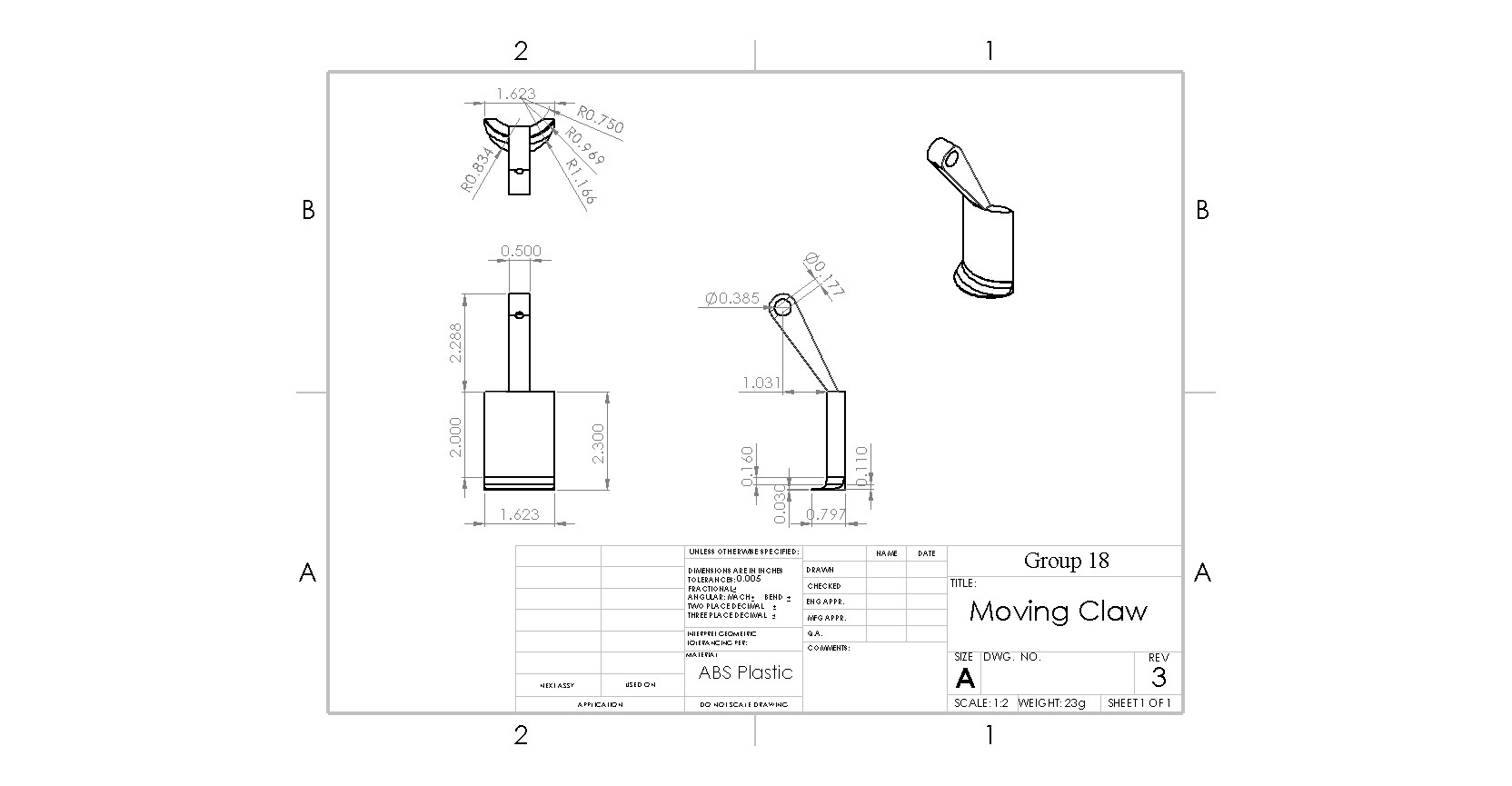
Our gripper has three claws and a middle rectangular section. We 3D printed the gripper to make it lighter and stronger. The claws run the height of the fidget spinner and onto the bottom curved section. Each section that is in contact with the fidget spinner is covered by friction tape. The friction tape allows the claws to better grip the fidget spinner. The side with two legs is rigid and screwed directly into the box. The arm that connects the claws to the box is triangular to account for the bending moment that occurs from the force. The side with one leg is connected to a wooden dowel and rotates when the motor is turned on, creating the force needed to keep the fidget spinner in place. We used screws to make sure this side of the claw stayed connected to the dowel and used rubber bands to keep the dowel from moving. There are two bearings on the box that allow the wooden dowel to move. We used wood instead of metal for the shaft because wood is much lighter. There are four holes in the top of the box, so that it can be attached to the arm.
Our gears are 3D printed using the resin in the Form2 printers. We decided to go with using the Form2 printer instead of ordering gears to reduce the weight of the overall part. The gears have a 2:1 ratio, which will allow us to generate enough torque and force to hold the fidget spinner in place while it swings. We used set screws in each of the gears to make sure that they did not start spinning and maintained the correct amount of torque.
Calculations
Total mass: 133g
Peak Force: 35.316 N
Factor of Safety with respect to dropping: 2.24
Factor of Safety with respect to component failure:
Contact stress in moving arm: 349.003
Bending in moving arm: 1.32
Bending of claws on gripper: 2.24
Small Gear: 50
Large Gear: 30
Stationary Arm: 1.104
Wooden Dowel: 8.565
Weakest Link:
The weakest link in the design is the arm that connects the side of the gripper with two claws to the box, as it has the lowest factor of safety. There is a lot of force on it and if it bends or breaks the fidget spinner will fall. We tried to increase the strength of the arm by making it a triangular prism.
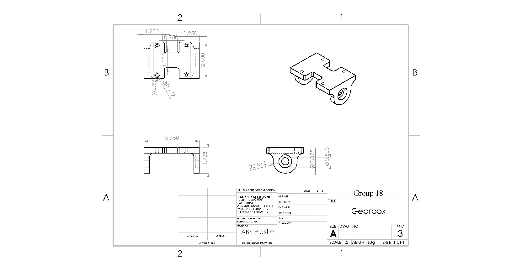
Documentation can be seen on the next page.